DTC C1241/41 Low Battery Positive Voltage or Abnormally High Battery Positive Voltage |

for Preparation Click here
DESCRIPTION
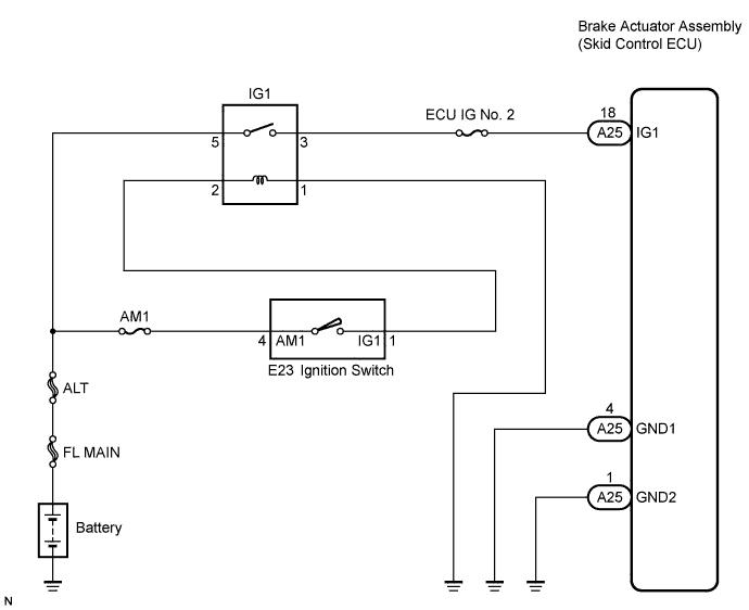
If a malfunction is detected in the power supply circuit of the brake actuator assembly (skid control ECU), the skid control ECU (housed in the actuator assembly) stores this DTC and the fail-safe function prohibits ABS operation (Click here).This DTC is output when the IG1 terminal voltage deviates from the normal condition due to a malfunction in the power supply or charging circuit such as the battery or alternator circuit, etc.
This DTC is cancelled when the IG1 terminal voltage returns to normal (only when the voltage returns to normal from a voltage lower than the specified value).
| DTC No. | DTC Detecting Condition | Trouble Area |
| C1241/41 | With vehicle speed more than 6 km/h (4 mph), when any of the following is detected:
|
|
WIRING DIAGRAM
INSPECTION PROCEDURE
- HINT:
- Check the condition of each related circuit connector before troubleshooting (Click here).
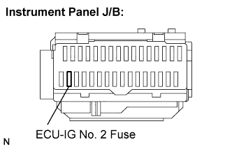
| 1.INSPECT FUSE (ECU-IG NO. 2 FUSE) |
Remove the ECU-IG No. 2 fuse from the instrument panel J/B.
 |
Measure the resistance according to the value(s) in the table below.
- Standard resistance:
Tester Connection Specified Condition ECU-IG No. 2 fuse Below 1 Ω (Continuity)
Install the fuse.
|
| ||||
| OK | |
| 2.INSPECT BATTERY |
Check the battery voltage.
- Standard voltage:
- 11 to 14 V
|
| ||||
| OK | |
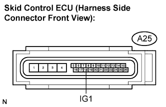
| 3.INSPECT SKID CONTROL ECU CONNECTOR (IG1 TERMINAL VOLTAGE) |
Disconnect the skid control ECU connector.
 |
Turn the ignition switch to the ON position.
Measure the voltage according to the value(s) in the table below.
- Standard voltage:
Tester Connection Condition Specified Condition A25-18 (IG1) -
Body groundIgnition switch on 10 to 14 V
|
| ||||
| OK | |
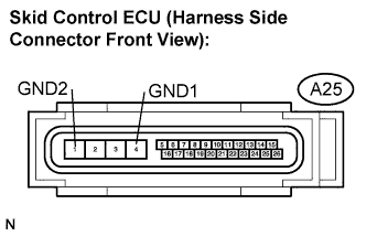
| 4.INSPECT SKID CONTROL ECU CONNECTOR (GND TERMINAL CONTINUITY) |
Measure the resistance according to the value(s) in the table below.
- Standard resistance:
Tester Connection Specified Condition A25-4 (GND1) - Body ground Below 1 Ω A25-1 (GND2) - Body ground Below 1 Ω
 |
Connect the connector.
|
| ||||
| OK | |
| 5.RECONFIRM DTC |
Clear the DTC (Click here).
Turn the ignition switch to the ON position.
Check if the same DTC is recorded (Click here).
- HINT:
- Reinstall the sensors, connectors, etc. and restore the vehicle to its prior condition before rechecking for DTCs.
- Result:
Condition Proceed to DTC (C1241/41) is output A DTC (C1241/41) is output (When troubleshooting in accordance with the PROBLEM SYMPTOMS TABLE) B DTC (C1241/41) is not output (When troubleshooting in accordance with the DTC CHART) C
|
| ||||
|
| ||||
| A | ||
| ||