REAR AXLE CARRIER > INSTALLATION |

for Preparation Click here
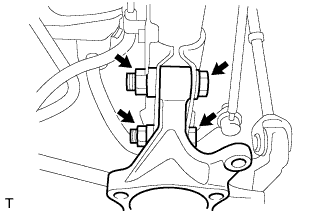
| 1. INSTALL REAR AXLE CARRIER SUB-ASSEMBLY |
Install the rear axle carrier sub-assembly to the shock absorber with the 2 bolts and 2 nuts.
- Torque:
- 180 N*m{ 1,836 kgf*cm , 133 ft.*lbf }
 |
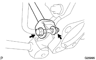
| 2. TEMPORARILY TIGHTEN REAR NO. 1 SUSPENSION ARM |
Temporarily tighten the rear No. 1 suspension arm with the bolt and nut.
- HINT:
- Insert the bolt from the rear side of the vehicle and temporarily tighten the bolt.
 |
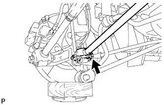
| 3. TEMPORARILY TIGHTEN REAR NO. 2 SUSPENSION ARM |
Temporarily tighten the rear No. 2 suspension arm with the bolt and nut.
- HINT:
- Insert the bolt from the rear side of the vehicle and temporarily tighten the bolt.
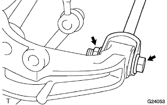 |
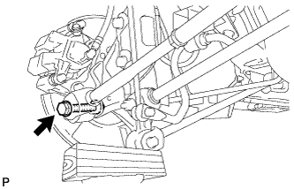
| 4. TEMPORARILY TIGHTEN REAR STRUT ROD |
Temporarily tighten the rear strut rod with the bolt and nut.
- HINT:
- Insert the bolt from the inside of the vehicle and temporarily tighten the bolt.
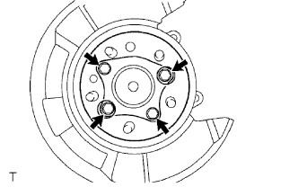
| 5. INSTALL REAR AXLE HUB AND BEARING ASSEMBLY |
Install the hub and bearing assembly with the 4 bolts.
- Torque:
- 80 N*m{ 816 kgf*cm , 59 ft.*lbf }
 |
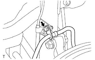
Connect the skid control sensor connector.
- NOTICE:
- Do not twist the sensor wire when connecting it.
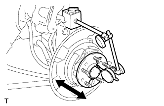
| 6. INSPECT REAR AXLE HUB BEARING LOOSENESS |
Using a dial indicator, check for looseness near the center of the axle hub.
- Maximum:
- 0.05 mm (0.0020 in.)
- NOTICE:
- Ensure that the dial indicator is set perpendicular to the measurement surface.
 |
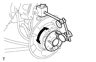
| 7. INSPECT REAR AXLE HUB RUNOUT |
Using a dial indicator, check for runout on the surface of the axle hub outside the hub bolt.
- Maximum:
- 0.07 mm (0.0027 in.)
- NOTICE:
- Ensure that the dial indicator is set perpendicular to the measurement surface.
 |
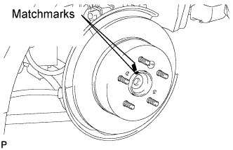
| 8. INSTALL REAR DISC |
Aligning the matchmarks, install the rear disc.
- HINT:
- When replacing the rear disc with a new one, select the installation position where the rear disc has the minimum runout.
 |
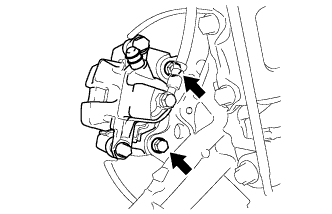
| 9. INSTALL REAR DISC BRAKE CALIPER ASSEMBLY |
Install the rear disc brake caliper with the 2 bolts.
- Torque:
- 62 N*m{ 630 kgf*cm , 46 ft.*lbf }
- NOTICE:
- Do not twist the brake hose when installing the rear disc brake caliper assembly LH.
 |
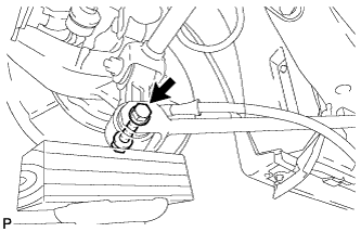
Install the rear flexible hose with the bolt.
- Torque:
- 19 N*m{ 192 kgf*cm , 14 ft.*lbf }
 |
| 10. INSTALL REAR WHEEL |
- Torque:
- 103 N*m{ 1,050 kgf*cm , 76 ft.*lbf }
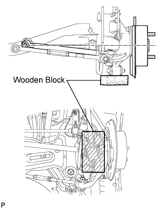
| 11. STABILIZE SUSPENSION |
Jack up the rear axle carrier, placing a wooden block to avoid damage. Apply load to the suspension so that the installed bolt of the rear suspension No. 1 arm (inner side of vehicle) is horizontally aligned with the center of the rear axle hub.
 |
| 12. FULLY TIGHTEN REAR NO. 1 SUSPENSION ARM |
Fully tighten the bolt.
- Torque:
- 100 N*m{ 1,020 kgf*cm , 74 ft.*lbf }
 |
| 13. FULLY TIGHTEN REAR NO. 2 SUSPENSION ARM |
Fully tighten the bolt.
- Torque:
- 100 N*m{ 1,020 kgf*cm , 74 ft.*lbf }
 |
| 14. FULLY TIGHTEN REAR STRUT ROD |
Fully tighten the bolt.
- Torque:
- 113 N*m{ 1,150 kgf*cm , 83 ft.*lbf }
 |
| 15. INSTALL REAR HEIGHT CONTROL SENSOR SUB-ASSEMBLY RH (w/ HID Headlight System) |
- HINT:
- Perform the procedure only when installing the RH side. (Click here)
| 16. ADJUST REAR WHEEL ALIGNMENT |
- HINT:
| 17. HEIGHT CONTROL SENSOR SIGNAL INITIALIZATION (w/ HID Headlight System) |
- HINT:
| 18. CHECK ABS SPEED SENSOR SIGNAL |
ABS: Click here
VSC: Click here