VALVE CLEARANCE > ADJUSTMENT |

for Preparation Click here
| 1. REMOVE FRONT WHEEL RH |
| 2. REMOVE ENGINE UNDER COVER LH |
| 3. REMOVE ENGINE UNDER COVER RH |
| 4. REMOVE FRONT FENDER APRON SUB-ASSEMBLY RH |
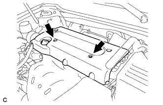
| 5. REMOVE NO. 1 ENGINE COVER |
Remove the 2 nuts and cover.
 |
| 6. REMOVE IGNITION COIL ASSEMBLY |
Remove the 4 bolts and 4 ignition coils.
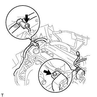
| 7. REMOVE CYLINDER HEAD COVER SUB-ASSEMBLY |
Remove the 2 bolts and disconnect the 2 engine wires.
 |
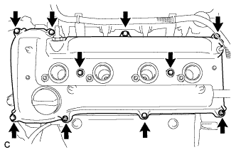
Remove the 8 bolts, 2 nuts, and the cylinder head cover.
 |
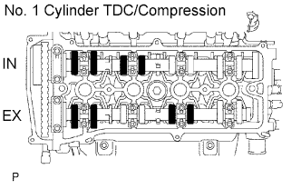
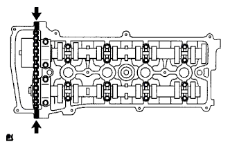
| 8. SET NO. 1 CYLINDER TO TDC/COMPRESSION |
Turn the crankshaft pulley until its groove and the timing mark "0" of the timing chain cover are aligned.
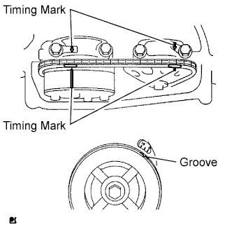 |
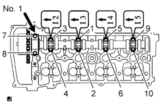
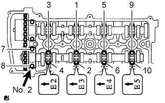
Check that each timing mark of the camshaft timing gear and sprocket is aligned with each timing mark located on the No. 1 and No. 2 bearing caps as shown in the illustration. If not, turn the crankshaft by 1 revolution (360°) to align the timing marks as above.
| 9. CHECK VALVE CLEARANCE |
Check only the valves indicated.
Using a feeler gauge, measure the clearance between the valve lifter and camshaft.
- Standard valve clearance (cold):
Item Standard Condition Intake 0.19 to 0.29 mm (0.0075 to 0.0114 in.) Exhaust 0.38 to 0.48 mm (0.0150 to 0.0189 in.)
Record any out-of-specification valve clearance measurements. They will be used later to determine the required replacement valve clearance lifters.
 |
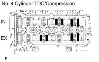
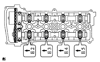
Turn the crankshaft 1 revolution (360°) and set the No. 4 cylinder to the TDC/compression.
Check only the valves indicated.
Using a feeler gauge, measure the clearance between the valve lifter and camshaft.
- Standard valve clearance (cold):
Item Standard Condition Intake 0.19 to 0.29 mm (0.0075 to 0.0114 in.) Exhaust 0.38 to 0.48 mm (0.0150 to 0.0189 in.)
Record any out-of-specification valve clearance measurements. They will be used later to determine the required replacement valve lifters.
 |
| 10. ADJUST VALVE CLEARANCE |
Remove the No. 2 camshaft (Click here).
Remove the camshaft (Click here).
Remove the valve lifters.
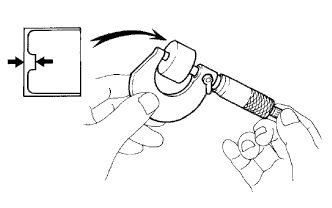
Using a micrometer, measure the thickness of the removed valve lifters.
 |
Calculate the thickness of a new lifter so that the valve clearance comes within the specified values.
- New lifter thickness:
Item Specification Intake A = B + (C - 0.24 mm (0.0095 in.)) Exhaust A = B + (C - 0.43 mm (0.0169 in.))
CALCULATION EXAMPLE (Intake):A New lifter thickness B Used lifter thickness C Measured valve clearance - Measured intake valve clearance = 0.40 mm (0.0158 in.)
(Measured - Specification = Excess clearance) - 0.40 mm (0.0158 in.) - 0.24 mm (0.0095 in.) = 0.16 mm (0.0063 in.)
- Measured used lifter measurement = 5.250 mm (0.2067 in.)
- New lifter thickness = 5.410 mm (0.2130 in.)
(Excess clearance + Used lifter thickness = Ideal new lifter) - 0.16 mm (0.0063 in.) + 5.250 mm (0.2067 in.) = 5.410 mm (0.2130 in.)
- Closest new lifter = 5.420 mm (0.2134 in.)
- Select No. 42 lifter
Select a new lifter with a thickness as close as possible to the calculated values.
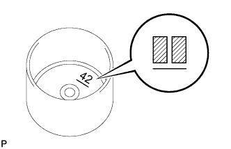
- HINT:
- Lifters are available in 35 sizes in increments of 0.020 mm (0.0008 in.), from 5.060 to 5.740 mm (0.1992 to 0.2260 in.).
- The identification number inside the valve lifters shows the value to 2 decimal places. (The illustration shows 5.420 mm (0.2134 in.)
 |
Valve lifter selection chart (intake).
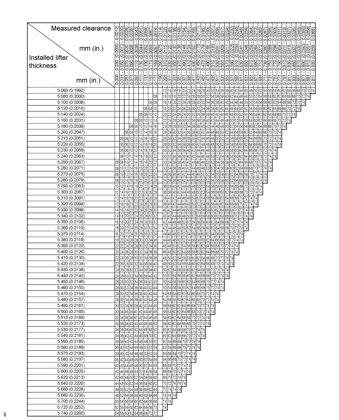
New lifter thickness Lifter No. Thickness
mm (in.)Lifter No. Thickness
mm (in.)Lifter No. Thickness
mm (in.)06 5.060 (0.1992) 30 5.300 (0.2087) 54 5.540 (0.2181) 08 5.080 (0.2000) 32 5.320 (0.2094) 56 5.560 (0.2189) 10 5.100 (0.2008) 34 5.340 (0.2102) 58 5.580 (0.2197) 12 5.120 (0.2016) 36 5.360 (0.2110) 60 5.600 (0.2205) 14 5.140 (0.2024) 38 5.380 (0.2118) 62 5.620 (0.2213) 16 5.160 (0.2031) 40 5.400 (0.2126) 64 5.640 (0.2220) 18 5.180 (0.2039) 42 5.420 (0.2134) 66 5.660 (0.2228) 20 5.200 (0.2047) 44 5.440 (0.2142) 68 5.680 (0.2236) 22 5.220 (0.2055) 46 5.460 (0.2150) 70 5.700 (0.2244) 24 5.240 (0.2063) 48 5.480 (0.2157) 72 5.720 (0.2252) 26 5.260 (0.2071) 50 5.500 (0.2165) 74 5.740 (0.2260) 28 5.280 (0.2079) 52 5.520 (0.2173) - - - Standard intake valve clearance (cold):
- 0.19 to 0.29 mm (0.0075 to 0.0114 in.)
The 5.250 mm (0.2067 in.) lifter is installed, and the measured clearance is 0.400 mm (0.0157 in.). Replace the 5.250 mm (0.2067 in.) lifter with a new No. 42 lifter.
Valve lifter selection chart (exhaust).
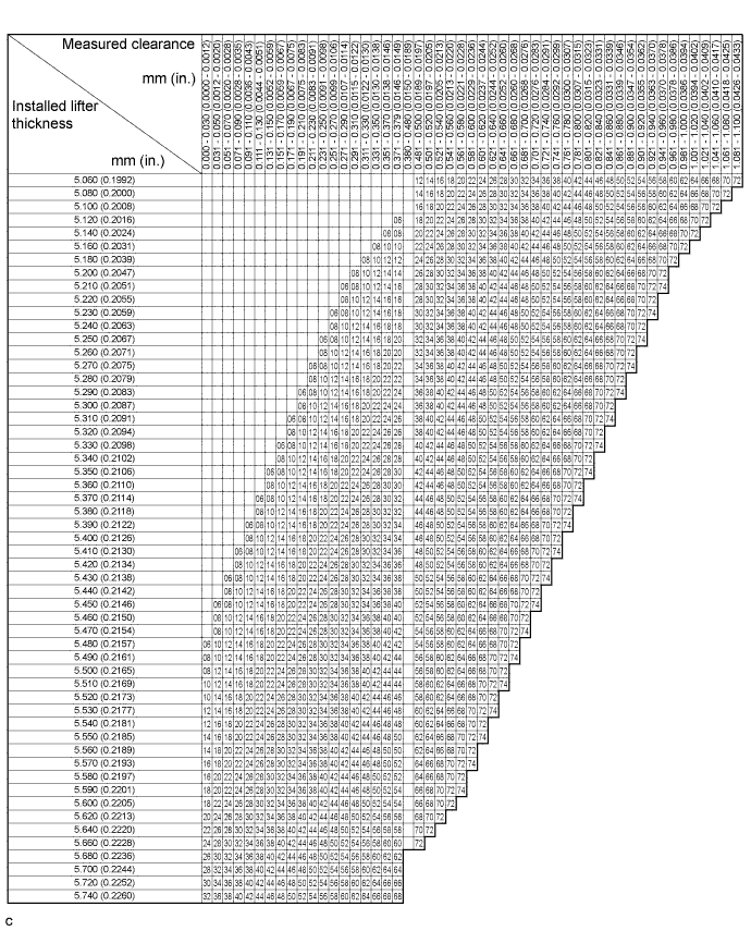
New lifter thickness Lifter No. Thickness
mm (in.)Lifter No. Thickness
mm (in.)Lifter No. Thickness
mm (in.)06 5.060 (0.1992) 30 5.300 (0.2087) 54 5.540 (0.2181) 08 5.080 (0.2000) 32 5.320 (0.2094) 56 5.560 (0.2189) 10 5.100 (0.2008) 34 5.340 (0.2102) 58 5.580 (0.2197) 12 5.120 (0.2016) 36 5.360 (0.2110) 60 5.600 (0.2205) 14 5.140 (0.2024) 38 5.380 (0.2118) 62 5.620 (0.2213) 16 5.160 (0.2031) 40 5.400 (0.2126) 64 5.640 (0.2220) 18 5.180 (0.2039) 42 5.420 (0.2134) 66 5.660 (0.2228) 20 5.200 (0.2047) 44 5.440 (0.2142) 68 5.680 (0.2236) 22 5.220 (0.2055) 46 5.460 (0.2150) 70 5.700 (0.2244) 24 5.240 (0.2063) 48 5.480 (0.2157) 72 5.720 (0.2252) 26 5.260 (0.2071) 50 5.500 (0.2165) 74 5.740 (0.2260) 28 5.280 (0.2079) 52 5.520 (0.2173) - - - Standard exhaust valve clearance (cold):
- 0.38 to 0.48 mm (0.0150 to 0.0189 in.)
The 5.340 mm (0.2102 in.) lifter is installed, and the measured clearance is 0.430 mm (0.0169 in.). Replace the 5.340 mm (0.2102 in.) lifter with a new No. 42 lifter.
Install the selected valve lifter.
| 11. INSTALL CAMSHAFT |
Apply a light coat of engine oil to the journal portion of the camshaft.
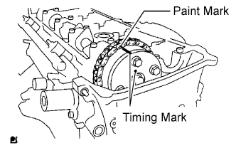
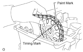
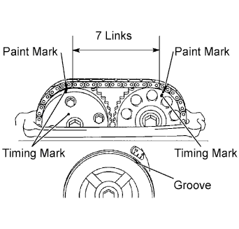
Install the timing chain onto the camshaft timing gear with the paint mark aligned with the timing mark on the camshaft timing gear as shown in the illustration.
 |
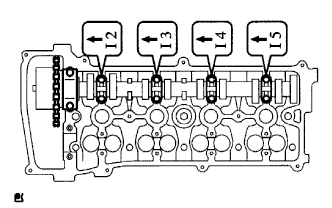
Examine the front marks and numbers, and check that the order is as shown in the illustration. Then install the bearing caps into the cylinder head.
 |
Apply a light coat of engine oil to the threads and under the heads of the bearing cap bolts.
Using several steps, uniformly tighten the 10 bearing cap bolts in the sequence shown in the illustration.
- Torque:
- No. 1 bearing cap:
- 30 N*m{ 301 kgf*cm , 22 ft.*lbf }
- No. 3 bearing cap:
- 9.0 N*m{ 92 kgf*cm , 80 in.*lbf }
 |
| 12. INSTALL NO. 2 CAMSHAFT |
Apply a light coat of engine oil to the journal portion of the No. 2 camshaft.
Put the No. 2 camshaft on the cylinder head with the paint mark of the chain aligned with the timing mark on the camshaft timing sprocket.
 |
While holding the No. 2 camshaft by hand, temporarily tighten the camshaft timing sprocket set bolt.
 |
Examine the front marks and numbers, and check that the order is as shown in the illustration. Then install the bearing caps onto the cylinder head.
 |
Apply a light coat of engine oil to the threads and under the heads of the bearing cap bolts.
Using several steps, uniformly tighten the 10 bearing cap bolts in the sequence shown in the illustration.
- Torque:
- No. 2 bearing cap:
- 30 N*m{ 301 kgf*cm , 22 ft.*lbf }
- No. 3 bearing cap:
- 9.0 N*m{ 92 kgf*cm , 80 in.*lbf }
 |
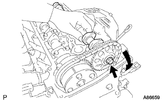
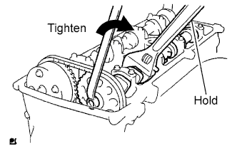
While holding the camshaft with a wrench, tighten the camshaft timing sprocket set bolt.
- Torque:
- 54 N*m{ 551 kgf*cm , 40 ft.*lbf }
- NOTICE:
- Be careful not to damage the valve lifter.
 |
Check that the paint marks on the chain are aligned with the timing marks on the camshaft timing gear and camshaft timing sprocket. Also, check that the crankshaft pulley groove is aligned with the timing mark "0" of the timing chain cover.
 |
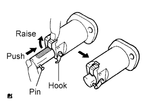
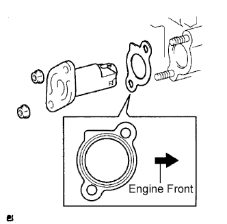
| 13. INSTALL NO. 1 CHAIN TENSIONER |
Release the ratchet pawl, then fully push in the plunger and hook the hook to the pin so that the plunger is in the position shown in the illustration.
 |
Install a new gasket and the chain tensioner with the 2 nuts.
- Torque:
- 9.0 N*m{ 92 kgf*cm , 80 in.*lbf }
- NOTICE:
- If the hook releases the plunger while the chain tensioner is being installed, set the hook again.
 |
Turn the crankshaft counterclockwise, then disconnect the plunger knock pin from the hook.
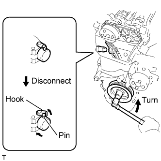 |
Turn the crankshaft clockwise, then check that the plunger is extended.
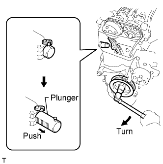 |
| 14. INSTALL CYLINDER HEAD COVER SUB-ASSEMBLY |
Remove any old packing material from the contact surface.
Apply seal packing to the 2 locations shown in the illustration.
- Seal packing:
- Toyota Genuine Seal Packing Block, Three Bond 1207B or Equivalent
- NOTICE:
- Remove any oil from the contact surface.
- Install the cylinder head cover within 3 minutes of applying seal packing.
- Do not add engine oil for at least 2 hours after installing the cylinder head cover.
 |
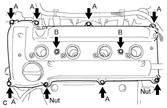
Install the cylinder head cover with the 8 bolts and 2 nuts.
- Torque:
- Bolt A:
- 11 N*m{ 112 kgf*cm , 8 ft.*lbf }
- Bolt B:
- 14 N*m{ 143 kgf*cm , 10 ft.*lbf }
- Nut:
- 11 N*m{ 112 kgf*cm , 8 ft.*lbf }
 |
Install the 2 engine wires with the 2 bolts.
- Torque:
- 8.4 N*m{ 86 kgf*cm , 74 in.*lbf }
 |
| 15. INSTALL IGNITION COIL ASSEMBLY |
Install the 4 ignition coils with the 4 bolts.
- Torque:
- 9.0 N*m{ 92 kgf*cm , 80 in.*lbf }
| 16. CHECK FOR ENGINE OIL LEAKS |
| 17. INSTALL NO. 1 ENGINE COVER |
Install the engine cover with the 2 nuts.
- Torque:
- 9.0 N*m{ 92 kgf*cm , 80 in.*lbf }
|
| 18. INSTALL FRONT FENDER APRON RH |
| 19. INSTALL ENGINE UNDER COVER LH |
| 20. INSTALL ENGINE UNDER COVER RH |
| 21. INSTALL FRONT WHEEL RH |