KNOCK SENSOR > REMOVAL |

for Preparation Click here
| 1. DISCHARGE FUEL SYSTEM PRESSURE |
- HINT:
| 2. DISCONNECT CABLE FROM NEGATIVE BATTERY TERMINAL |
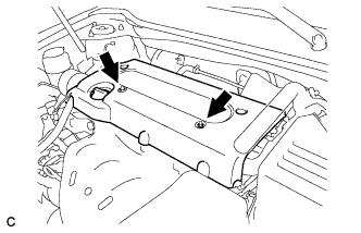
| 3. REMOVE NO. 1 ENGINE COVER SUB-ASSEMBLY |
Remove the 2 nuts and cover.
 |
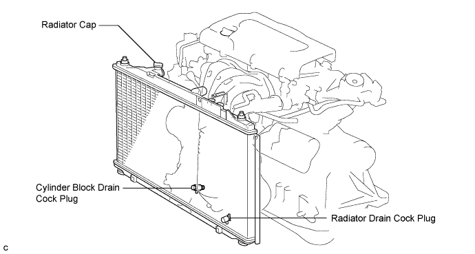
| 4. DRAIN ENGINE COOLANT |
- NOTICE:
- Do not remove the radiator cap sub-assembly while the engine and radiator are still hot. Pressurized, hot engine coolant and steam may be released and cause serious burns.
Remove the radiator cap sub-assembly from the radiator assembly.
Loosen the radiator drain cock plug and cylinder block drain cock plug, then drain the coolant.
- HINT:
- Collect the coolant in a container and dispose of it according to the regulations in your area.
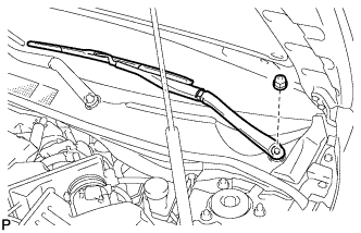
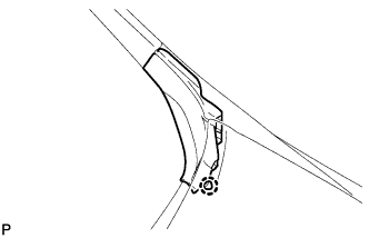
| 5. REMOVE WINDSHIELD WIPER ARM AND BLADE ASSEMBLY LH |
Remove the nut and the front wiper arm and blade assembly LH.
 |
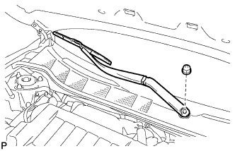
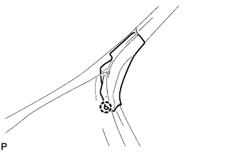
| 6. REMOVE WINDSHIELD WIPER ARM AND BLADE ASSEMBLY RH |
Remove the nut and the front wiper arm and blade assembly RH.
 |
| 7. REMOVE FRONT FENDER TO COWL SIDE SEAL LH |
Disengage the claw and remove the front fender to cowl side seal LH.
 |
| 8. REMOVE FRONT FENDER TO COWL SIDE SEAL RH |
Disengage the claw and remove the front fender to cowl side seal RH.
 |
| 9. REMOVE COWL TOP VENTILATOR LOUVER SUB-ASSEMBLY |
Remove the 2 clips.
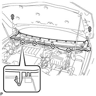 |
Disengage the 4 claws and remove the cowl top ventilator louver sub-assembly.
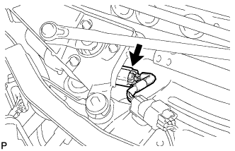
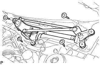
| 10. REMOVE WINDSHIELD WIPER MOTOR AND LINK |
Disconnect the connector.
 |
Remove the 4 bolts and the windshield wiper motor and link assembly.
 |
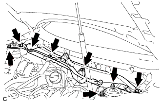
| 11. REMOVE OUTER COWL TOP PANEL SUB-ASSEMBLY |
Remove the 4 bolts, 4 nuts and outer cowl top panel sub-assembly.
 |
| 12. REMOVE AIR CLEANER CAP SUB-ASSEMBLY |
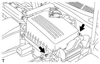
Disconnect the mass air flow meter connector (*1).
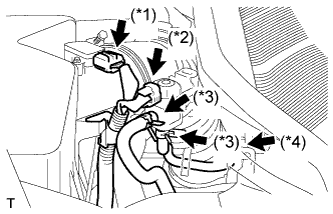 |
Disconnect the purge VSV connector (*2).
Disconnect the 2 purge VSV vacuum hoses (*3).
Disconnect the purge line hose from the clamp (*4).
Disconnect the No. 2 ventilation hose from the air cleaner hose.
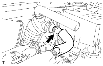 |
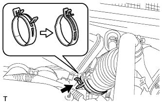
Lock the No. 1 air cleaner hose clamp, and then disconnect the No. 1 air cleaner hose from the throttle body.
 |
Remove the 2 bolts and air cleaner cap.
 |
Remove the air cleaner filter element from the air cleaner case.
| 13. REMOVE AIR CLEANER CASE SUB-ASSEMBLY |
Disconnect the hose clamp.
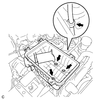 |
Remove the 3 bolts and air cleaner case.
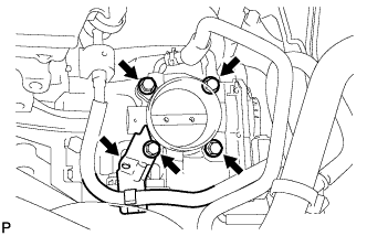
| 14. REMOVE THROTTLE BODY |
Disconnect the throttle position sensor connector and wire harness clamp.
 |
Remove the 4 bolts, and then remove the fuel pipe support and throttle body.
 |
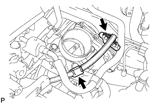
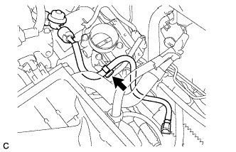
Disconnect the purge line hose from the throttle body.
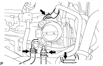 |
Disconnect the water by-pass hose from the throttle body.
Disconnect the No. 2 water by-pass hose from the throttle body.
Disconnect the No. 1 throttle body hose from the throttle body.
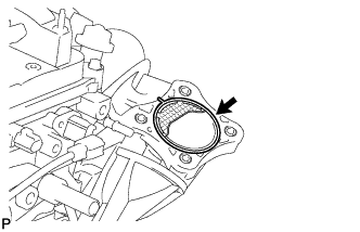
Remove the gasket from the intake manifold.
 |
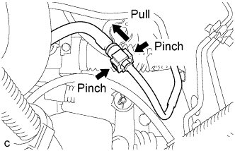
| 15. DISCONNECT FUEL TUBE |
Remove the No. 1 fuel pipe clamp.
- NOTICE:
- Check for foreign matter on the pipe and around the connector before disconnecting the quick connector. Clean the connector if necessary.
 |
If the connector and pipe are stuck, pinch the connector, and push and pull the pipe to disconnect them.
- NOTICE:
- Do not use any tools in this procedure.
- Check for foreign matter on the sealing surface of the disconnected pipe. Clean it if necessary.
 |
Separate the fuel tube from the fuel hose clamp.
 |
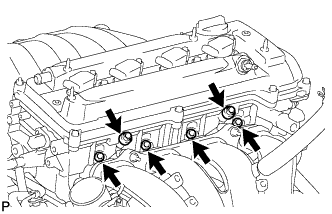
| 16. REMOVE FUEL DELIVERY PIPE WITH INJECTOR |
Remove the 2 wire harness clamps.
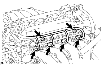 |
Disconnect the 4 fuel injector connectors.
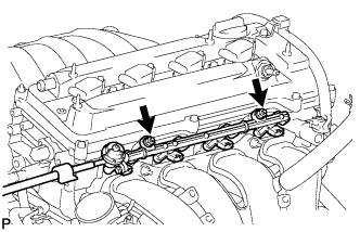
Remove the 2 bolts, then remove the fuel delivery pipe together with the 4 fuel injectors.
- NOTICE:
- Be careful not to drop the fuel injectors when removing the fuel delivery pipe.
 |
Remove the 2 delivery pipe spacers from the cylinder head.
 |
Remove the 4 insulators from the cylinder head.
| 17. REMOVE INTAKE MANIFOLD |
Disconnect the union to check valve hose from the brake booster.
Disconnect the camshaft timing oil control valve connector.
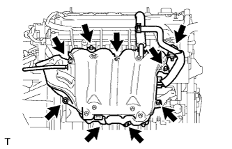 |
Remove the wire harness clamp.
Remove the union to check valve hose from the vacuum hose clamp.
Remove the 5 bolts, 2 nuts and intake manifold.
Remove the gasket from the intake manifold.
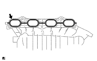 |
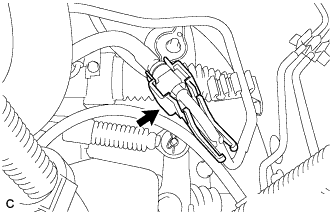
| 18. REMOVE KNOCK SENSOR |
Disconnect the knock sensor connector.
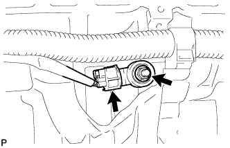 |
Remove the nut and knock sensor.