SKID CONTROL SENSOR > INSTALLATION |

for Preparation Click here
| 1. INSTALL SKID CONTROL SENSOR |
Clean the contact surface between the rear axle hub and bearing assembly and a new skid control sensor.
- NOTICE:
- Prevent foreign matter from attaching to the skid control sensor rotor.
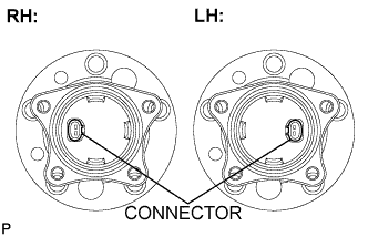 |
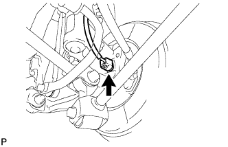
Place the skid control sensor on the rear axle hub and bearing assembly so that the connector is positioned as shown in the illustration.
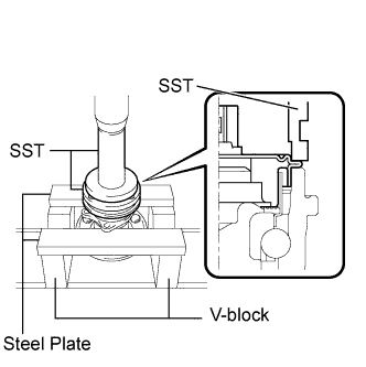
Using SST, a press, 2 V-blocks, and 2 steel plates, install the skid control sensor to the rear axle hub and bearing assembly.
- SST
- 09309-36010
09213-58013
- NOTICE:
- Keep the skid control sensor away from magnets.
- Do not use a hammer on the skid control sensor.
- Check that there is no foreign matter such as iron chips on the detecting portion of the skid control sensor.
- Slowly press the skid control sensor straight.
 |
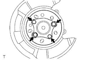
| 2. INSTALL REAR AXLE HUB AND BEARING ASSEMBLY WITH SKID CONTROL SENSOR |
Install the hub and bearing assembly with the 4 bolts.
- Torque:
- 80 N*m{ 816 kgf*cm , 59 ft.*lbf }
 |
Connect the skid control sensor connector.
- NOTICE:
- Do not twist the sensor wire when connecting it.
| 3. INSPECT REAR AXLE HUB BEARING LOOSENESS |
Using a dial indicator, check for looseness near the center of the axle hub.
- Maximum:
- 0.05 mm (0.0020 in.)
- NOTICE:
- Ensure that the dial indicator is set perpendicular to the measurement surface.
 |
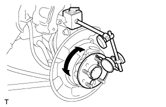
| 4. INSPECT REAR AXLE HUB RUNOUT |
Using a dial indicator, check for runout on the surface of the axle hub outside the hub bolt.
- Maximum:
- 0.07 mm (0.0027 in.)
- NOTICE:
- Ensure that the dial indicator is set perpendicular to the measurement surface.
 |
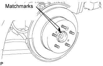
| 5. INSTALL REAR DISC |
Aligning the matchmarks, install the rear disc.
- HINT:
- When replacing the rear disc with a new one, select the installation position where the rear disc has the minimum runout.
 |
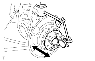
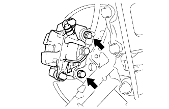
| 6. INSTALL REAR DISC BRAKE CALIPER ASSEMBLY |
Install the rear disc brake caliper with the 2 bolts.
- Torque:
- 62 N*m{ 630 kgf*cm , 46 ft.*lbf }
- NOTICE:
- Do not twist the brake hose when installing the rear disc brake caliper assembly LH.
 |
Install the rear flexible hose with the bolt.
- Torque:
- 19 N*m{ 192 kgf*cm , 14 ft.*lbf }
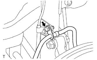 |
| 7. CONNECT SKID CONTROL SENSOR WIRE |
Connect the connector to the skid control sensor.
 |
| 8. INSTALL REAR WHEEL |
- Torque:
- 103 N*m{ 1,050 kgf*cm , 76 ft.*lbf }
| 9. INSPECT AND ADJUST REAR WHEEL ALIGNMENT |
- HINT:
| 10. CHECK SPEED SENSOR SIGNAL |
- HINT:
- without VSC (Click here)
- with VSC (Click here)