DTC P0420 Catalyst System Efficiency Below Threshold (Bank 1) |

for Preparation Click here
DESCRIPTION
The ECM uses the sensors mounted in front of and behind the Three-Way Catalytic Converter (TWC) to monitor its efficiency.The first sensor, the Air-Fuel Ratio (A/F) sensor, sends pre-catalyst information to the ECM. The second sensor, the Heated Oxygen (HO2) sensor, sends post-catalyst information to the ECM.
In order to detect any deterioration in the TWC, the ECM calculates the Oxygen Storage Capacity (OSC) of the TWC. This calculation is based on the voltage output of the HO2 sensor while performing active air- fuel ratio control, rather than the conventional detecting method, which uses the locus ratio.
The OSC value is an indication of the oxygen storage capacity of the TWC. When the vehicle is being driven with a warm engine, active air-fuel ratio control is performed for approximately 15 to 20 seconds. When it is performed, the ECM deliberately sets the air-fuel ratio to lean or rich levels. If the rich-lean cycle of the HO2 sensor is long, the OSC becomes greater. There is a direct correlation between the OSCs of the HO2 sensor and the TWC.
The ECM uses the OSC value to determine the state of the TWC. If any deterioration has occurred, it illuminates the MIL and sets the DTC.
| DTC No. | DTC Detection Condition | Trouble Area |
| P0420 | OSC value smaller than standard value under active air-fuel ratio control (2 trip detection logic) |
|
CONFIRMATION DRIVING PATTERN
- HINT:
- Performing this confirmation pattern will activate the catalyst monitor. This is very useful for verifying completion of a repair.
Connect the intelligent tester to the DLC3.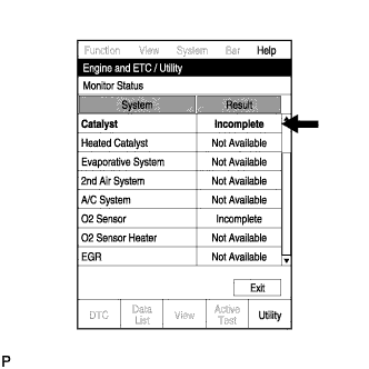
- Turn the ignition switch to the ON position.
- Turn the tester on.
- Clear the DTCs (if set) (Click here).
- Enter the check mode (Click here).
- Select the following menu items: Powertrain / Engine and ECT / Utility / Monitor Status.
- Check that "Catalyst" is "Incomplete".
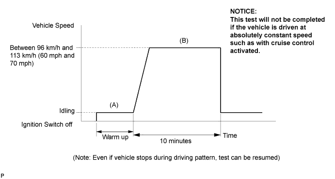
- Start the engine and warm it up. (Proceed to "A")
- Drive the vehicle at between 96 km/h and 113 km/h (60 mph and 70 mph) for at least 10 minutes. (Proceed to "B")
- Note the state of the "Readiness Tests" items. Those items will change to "Complete" as the catalyst monitor operates.
- On the tester, select the following menu items: Powertrain / Engine and ECT / DTC.
- HINT:
- If "Catalyst" does not change to "Complete", and any pending DTCs fail to set, extend the driving time.
CONDITIONING FOR SENSOR TESTING
- HINT:
- Perform the operation with the engine speeds and time durations described below prior to checking the waveforms of the A/F and HO2 sensors. This is in order to activate the sensors sufficiently to obtain the appropriate inspection results.
- Connect the intelligent tester to the DLC3. (Proceed to "A")
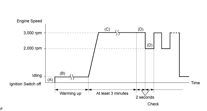
- Start the engine and warm it up with all the accessories switched OFF, until the engine coolant temperature stabilizes. (Proceed to "B")
- Run the engine at an engine speed of between 2,500 rpm and 3,000 rpm for at least 3 minutes. (Proceed to "C")
- While running the engine at 3,000 rpm and 2,000 rpm alternating at 2 second intervals, check the waveforms of the A/F and HO2 sensors using the tester. (Proceed to "D")
- HINT:
- If either voltage output of the Air-Fuel Ratio (A/F) or Heated Oxygen (HO2) sensor does not fluctuate, or there is a noise in the waveform of either sensor, the sensor may be malfunctioning.
- If the voltage outputs of both the sensors remain lean or rich, the air-fuel ratio may be extremely lean or rich. In such cases, perform the following "Control the Injection Volume for A/F Sensor" using the intelligent tester.
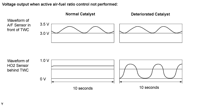
- If the Three-Way Catalytic Converter (TWC) has deteriorated, the HO2 sensor (located behind the TWC) voltage output fluctuates up and down frequently, even under normal driving conditions (active air-fuel ratio control is not performed).
INSPECTION PROCEDURE
- HINT:
- Read freeze frame data using the intelligent tester. The ECM records vehicle and driving condition information as freeze frame data the moment a DTC is stored. When troubleshooting, freeze frame data can help determine if the vehicle was moving or stationary, if the engine was warmed up or not, if the air-fuel ratio was lean or rich, and other data from the time the malfunction occurred.
| 1.CHECK ANY OTHER DTCS OUTPUT (IN ADDITION TO DTC P0420) |
Connect the intelligent tester to the DLC3.
Turn the ignition switch to the ON position and turn the tester on.
Select the following menu items: Powertrain / Engine and ECT / DTC.
Read the DTCs.
- Result:
Display (DTC Output) Proceed to P0420 A P0420 and other DTCs B
- HINT:
- If any DTCs other than P0420 are output, troubleshoot those DTCs first.
|
| ||||
| A | |
| 2.PERFORM ACTIVE TEST USING INTELLIGENT TESTER (A/F CONTROL) |
Connect the intelligent tester to the DLC3.
Start the engine and turn the tester on.
Warm up the engine at an engine speed of 2,500 rpm for approximately 90 seconds.
On the tester, select the following menu items: Powertrain / Engine and ECT / Active Test / Control the Injection Volume for A/F Sensor.
Perform the "Control the Injection Volume for A/F Sensor" operation with the engine in an idling condition (press the RIGHT or LEFT button to change the fuel injection volume).
Monitor the voltage outputs of the A/F and HO2 sensors (AFS B1 S1 and O2S B1 S2) displayed on the tester.
- Result:
- A/F sensor reacts in accordance with increases and decreases in fuel injection volume:
- +25% = Rich output:
- Less than 3.0 V
- -12.5% = Lean output:
- More than 3.35 V
- NOTICE:
- The A/F sensor has an output delay of a few seconds and the HO2 sensor has a maximum output delay of approximately 20 seconds.
| Case | A/F Sensor (Sensor 1) Output Voltage | HO2 Sensor (Sensor 2) Output Voltage | Main Suspected Trouble Area | ||
| 1 | Injection Volume +25% -12.5% |  | Injection Volume +25% -12.5% | |
|
| Output Voltage More than 3.35 V Less than 3.0 V |  | Output Voltage More than 0.5 V Less than 0.4 V |  | ||
| 2 | Injection Volume +25% -12.5% | | Injection Volume +25% -12.5% | |
|
| Output Voltage Almost no reaction |  | Output Voltage More than 0.5 V Less than 0.4 V | | ||
| 3 | Injection Volume +25% -12.5% | | Injection Volume +25% -12.5% | |
|
| Output Voltage More than 3.35 V Less than 3.0 V | | Output Voltage Almost no reaction | | ||
| 4 | Injection volume +25% -12.5% | | Injection Volume +25% -12.5% | | Extremely rich or lean actual air-fuel ratio
|
| Output Voltage Almost no reaction | | Output Voltage Almost no reaction | | ||
- Following the "Control the Injection Volume for A/F Sensor" procedure enables technicians to check and graph the voltage outputs of both the A/F and HO2 sensors.
- To display the graph, select the following menu items on the tester: Powertrain / Engine and ECT / Active Test / Control the Injection Volume for A/F Sensor / Enter / View / AFS B1 S1 and O2S B1 S2.
- Result:
Result Proceed to Case 1 A Case 2 B Case 3 C Case 4 D
|
| ||||
|
| ||||
|
| ||||
| A | |
| 3.CHECK FOR EXHAUST GAS LEAK |
- OK:
- No gas leakage.
|
| ||||
| OK | ||
| ||
| 4.CHECK FOR EXHAUST GAS LEAK |
- OK:
- No gas leakage.
|
| ||||
| OK | ||
| ||